Wang 600 Technology
The 600 series machines were the first to use semiconductor RAM, Wang abandoning its historic association with magnetic core storage and adopting the very new technology of MOS RAM. IC technology was not quite ready to serve for the microcode ROM when the 600 was introduced and early numbers used wire braid ROM like the 700 series. Later numbers had MOS ROM to replace the large and expensive wire braid ROMs.
Hardware and Power
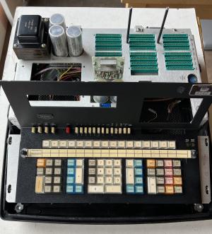
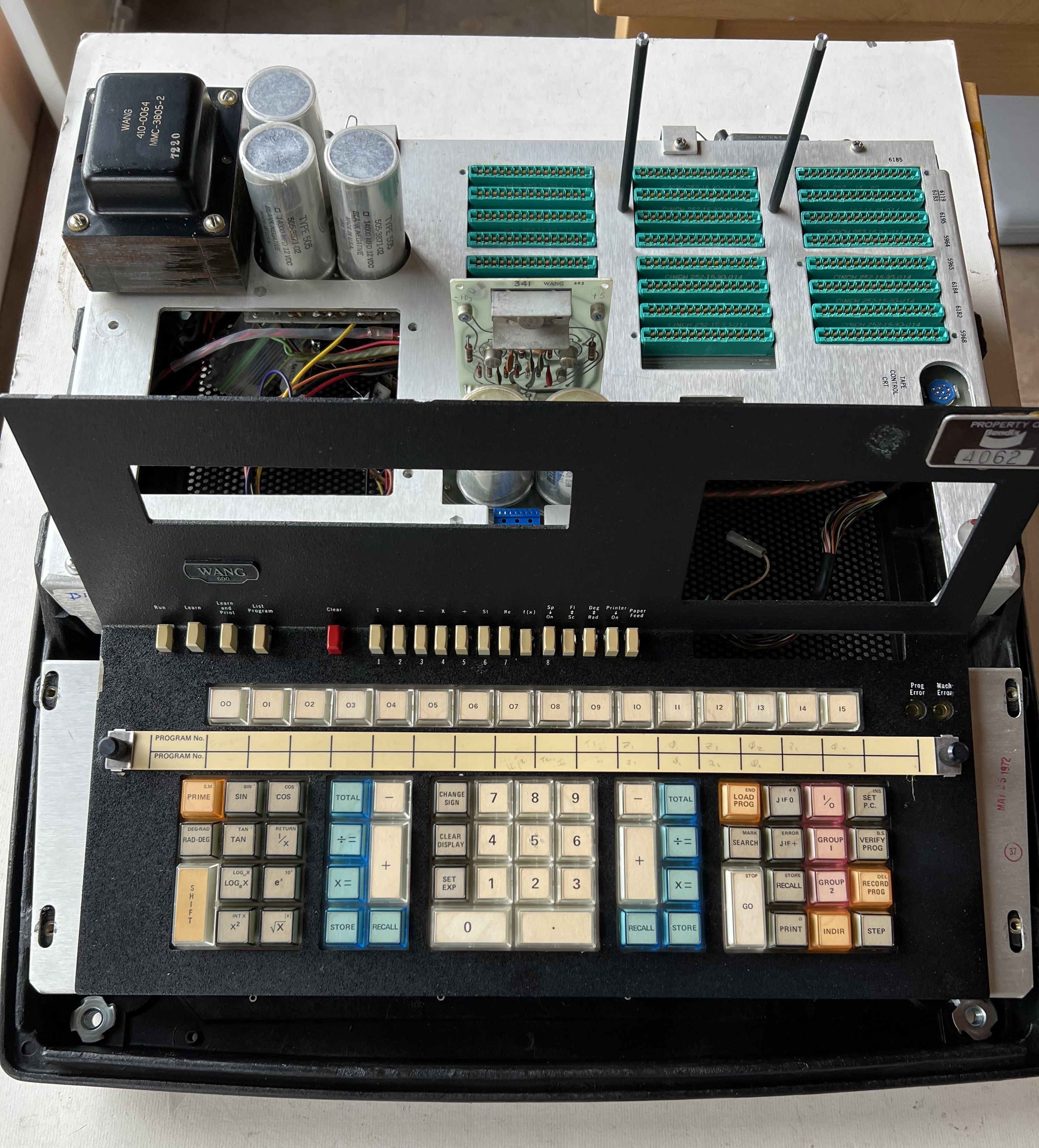
The power supply provides floating outputs of +12, +5, -11.5, -12 and +250 for the Panaplex. The + and - 12 are crudely regulated with zeners and resistors. The -11.5 for the Mostel DRAMs and the +5 for the TTL chips have more sophisticated regulation based on the classic 723 regulator IC. Both of these regulators use series-pass topology and can generate over-voltage if the pass transistors fail short-circuit.
Voltage Clamps
Over-voltage on the -11.5 supply may damage the Mostek DRAMs and these are increasingly difficult to find. Over-voltage on the +5v could place several hundred TTL chips at risk.
With these risks in mind, a MOSFET voltage clamp was added to each of these supplies to prevent serious downstream damage in the event of pass transistor failure.
Electronics
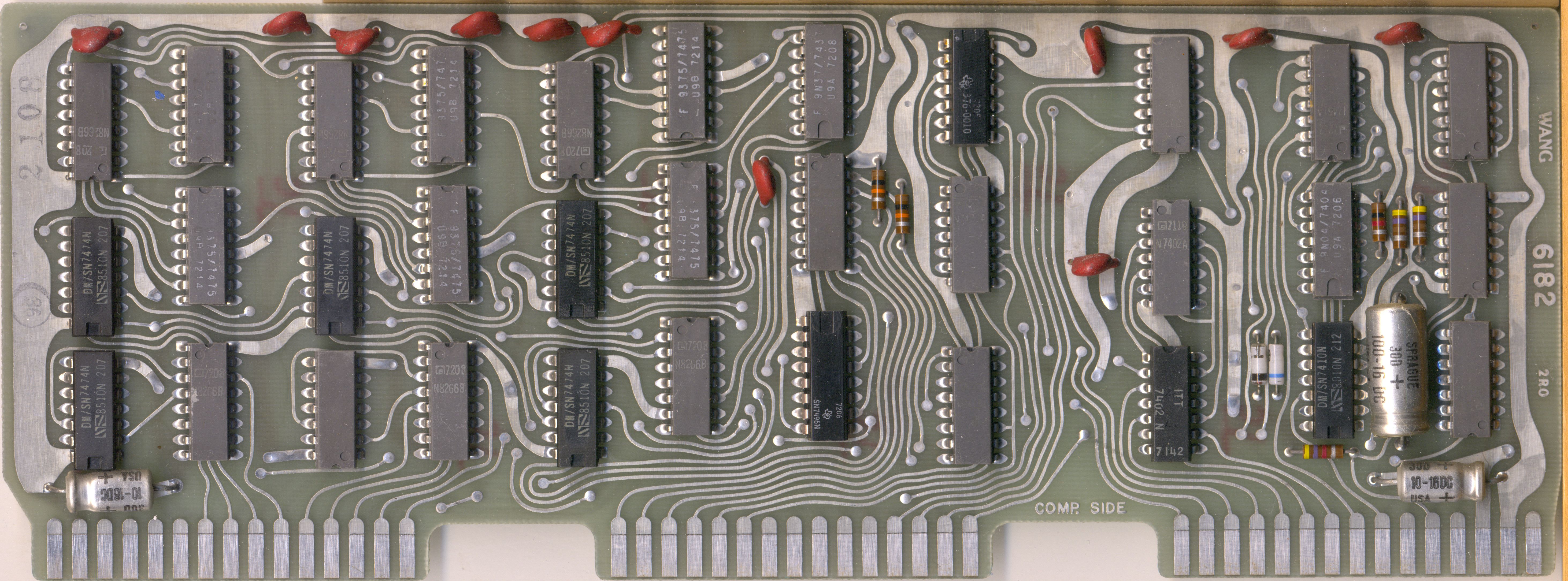
Computation is done in bit-serial fashion using a 1-bit wide ALU that can perform add, subtract, AND, OR and complement. There is very limited hardware support for peripherals - display refresh is performed by microcode and if the code does not run, there is no display. Printing likewise requires the microcode to send properly timed data streams to activate print hammers at the correct instant. Recording and decoding of casette tape data is also done entirely in microcode.
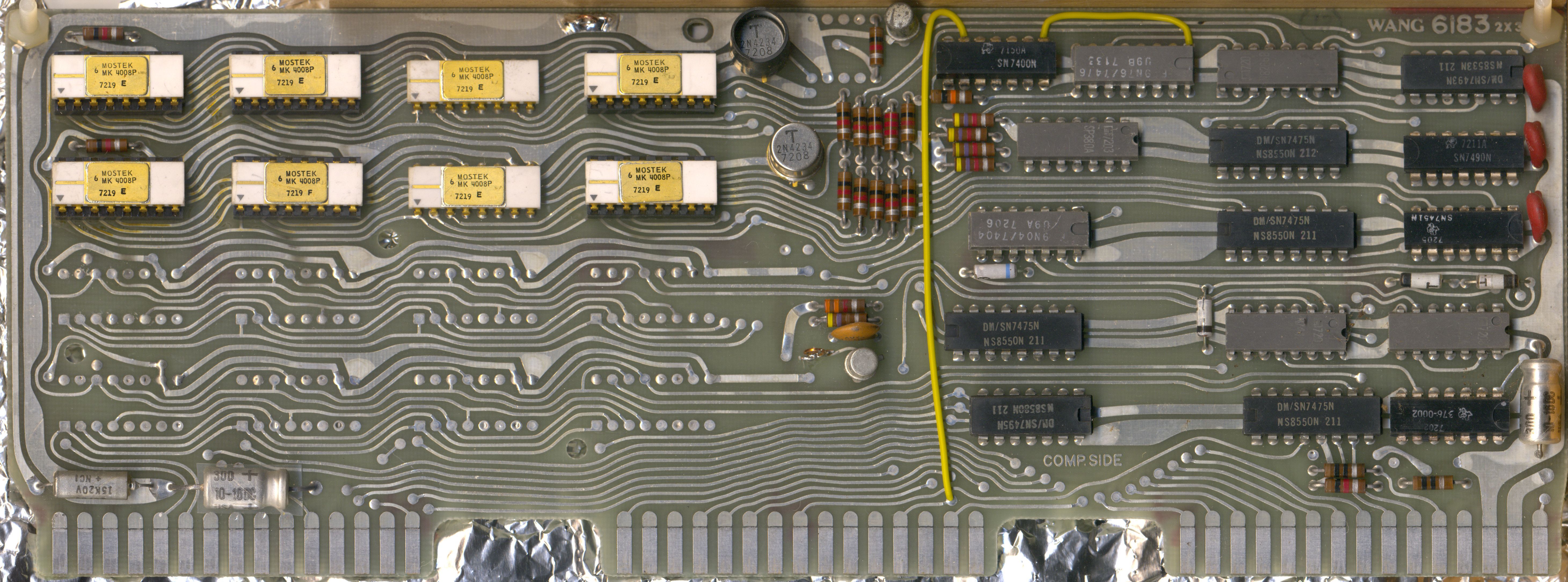
The RAM board has circuits to switch off the -11.5v supply between memory accesses. This technique is described in the Mostek datasheet as a power saving strategy and it’s true that early RAM chips did tend to run hot. Nevertheless, power saving does seem rather unnecesary in a mains powered machine with a maximum of 16 RAM chips. Perhaps the overheating problems of early 700 series machines were still fresh in the minds of the designers and they were keen to take all opportunities in the 600 series to reduce power dissipation and consequent heating.
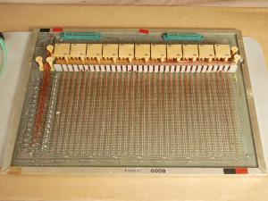

The ROM board decodes the address into 64 channels, each channel then emits 32 fine copper wires (64 x 32 = 2048) and each of these is routed through or beside 42 sense transformers. Each transformer represents one ROM data bit. At each ROM read a controlled current pulse is delivered to the single wire that is defined by the current ROM address. Where the wire passes through a sense transformer it will generate an output for that ROM bit, transformers that are bypassed will not generate an output. These outputs are latched to form and hold the 42-bit ROM data word.
The wires are approximately 60cm long and 2048 x 60cm is 1.3km or three quarters of a mile of wire, all of which must be threaded accurately and without breaks. Failure of a single wire or a single one of 2048 steering diodes will cause the ROM to lose a word. If this were to occur in the code for a little used function then the machine may crash or produce an error in that function but if the failure was in core microcode (eg display refresh) then the machine would most likely be rendered dead.
Microcode
The 600 series has microcode that is similar to the 700 series. The microcode word is 42 bits wide (vs 43 bits in 700 series) and this controls internal data paths and ALU capabilities that are very similar to the 700 series. The microcode ROM is 2048 42-bit words ( = 86016 bits = 10752 bytes).
There is no instruction address register, instead each microcode word contains the address of the next word to be executed. Execution typically jumps from place to place rather than following an address sequence. Each microcode word has nine bits that define the upper bits of the ’next address’ and then two three-bit conditional fields. Each conditional field reduces to 0 or 1 according to machine state at that instant. The effect is that each microcode instruction specifies a base location for the next instruction, but the exact address may be offset by 0, 1, 2 or 3 additional locations according to machine state. One further microcode bit acts as a subroutine flag, causing the current adress to be stored on a two-level LIFO hardware stack before proceeding to the next address. Thus 16 of 42 bits are dedicated to microcode sequencing leaving 26 bits for machine control.
The controllable functions are pretty basic being
- selection of two ALU sources and one destination
- ALU operation - add, subtract, AND, OR, complement
- load or store 4-bit values from/to RAM, ROM or peripherals
- load a 4-bit constant
- direct control of display, printer or tape
The biggest difference in 600 series microcode is the subroutine jump bit and associated 2 level hardware stack. The 700 hardware does not support subroutines and this must have been a very welcome enhancement for the 600 series microcode developers.
All functions including keyboard scanning, computation, tape recording or decoding and print hammer firing are directly controlled by microcode with very little helper hardware. The display is generated by sequential loading of each digit from memory to the display driver and then a pause before the next digit is loaded. The refresh rate is approx 90Hz.
Any failure in ROM or microcode engine will result in a dead machine with dark display and no keyboard response. This makes fault-finding challenging because the majority of faults produce the same symptom - dead machine. In most cases board swapping would be the fastest way to localise faults and restore the machine. Without this option fault-finding can be a slow process.